




Value Added Sevices
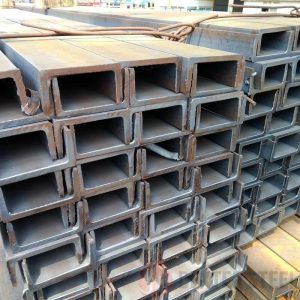
Parallel Flange Channels are used in UK, Australia, and NZ construction for simpler connections. Processing must ensure dimensional accuracy and straightness to match detailed fabrication drawings.
Frequently Asked Questions
Structural engineers and fabrication contractors typically raise specific technical questions when sourcing PFC channels because these profiles must match engineering specifications precisely. Buyers often focus on dimensional accuracy, structural compatibility with design standards, and fabrication efficiency during assembly.
What defines a PFC steel channel profile
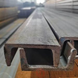
PFC channels are structural steel sections characterized by parallel flange surfaces rather than tapered flanges. This design simplifies bolted and welded connections in structural assemblies.
Where are PFC channels commonly used
PFC channels are widely used in structural frames for buildings, industrial facilities, bridges, and infrastructure projects, particularly in regions following British or Commonwealth engineering standards.
How do PFC channels differ from UPN channels
The key difference is flange geometry. PFC channels have parallel flanges, while UPN channels have tapered flanges. This difference affects connection design and structural calculations.
Can PFC channels be easily welded or bolted
Yes. The parallel flange design allows easier alignment during welding or bolting, which improves fabrication efficiency in structural steel assemblies.
Why do engineers specify PFC channels in certain projects
Engineers may select PFC channels when design standards require British or Commonwealth structural specifications, or when parallel flange geometry simplifies connection design.
PFC channels are structural steel sections characterized by parallel flange surfaces rather than tapered flanges. This design simplifies bolted and welded connections in structural assemblies.
PFC channels are widely used in structural frames for buildings, industrial facilities, bridges, and infrastructure projects, particularly in regions following British or Commonwealth engineering standards.
The key difference is flange geometry. PFC channels have parallel flanges, while UPN channels have tapered flanges. This difference affects connection design and structural calculations.
Yes. The parallel flange design allows easier alignment during welding or bolting, which improves fabrication efficiency in structural steel assemblies.
Engineers may select PFC channels when design standards require British or Commonwealth structural specifications, or when parallel flange geometry simplifies connection design.
Related Glossaries
A flange design where the inner and outer surfaces remain parallel rather than tapered. This geometry simplifies bolted connections and improves alignment during structural fabrication.
The engineering process of preparing precise drawings that define dimensions, connections, and fabrication requirements for steel structures.
A structural joining method where steel components are connected using high-strength bolts rather than welding, often used in large structural assemblies.
A flange design where the inner and outer surfaces remain parallel rather than tapered. This geometry simplifies bolted connections and improves alignment during structural fabrication.
The engineering process of preparing precise drawings that define dimensions, connections, and fabrication requirements for steel structures.
A structural joining method where steel components are connected using high-strength bolts rather than welding, often used in large structural assemblies.
Industries Served
Primary Industries: Commercial Framing, Modular Construction
Structural Fabrication
- Floor beams and joists
- Portal frame structures
- Lintels and edge beams
Modular & Prefab
- Structural skeletons
- Frames
Mining & Quarrying
- Walkways and access platforms