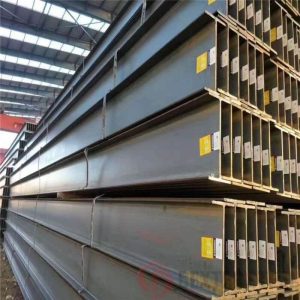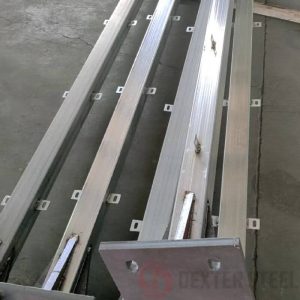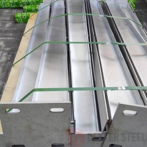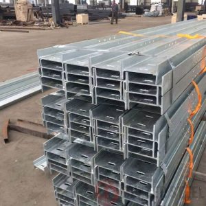




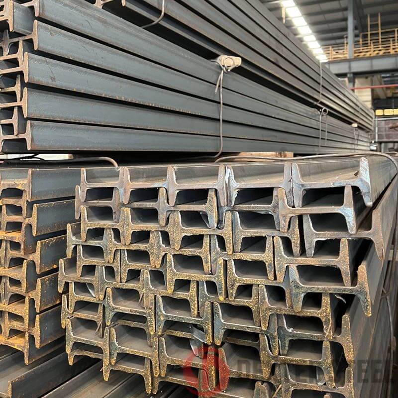
I beams are designed with tapered flanges and a central web that efficiently carries bending forces. This structural form concentrates material where stress is highest, allowing the beam to support loads while maintaining relatively low weight.
Another characteristic of I beams is their widespread availability in standard rolled sizes. Because the profile has been used in construction for many decades, many service centers keep these sections in stock for fast project supply.
I beams are also easy to fabricate and connect within structural systems. Common connection methods include welding, bolting, and plate connections, making them suitable for a variety of building frameworks.
However, compared with wide flange beams, I beams typically provide lower load capacity for the same depth due to the tapered flange geometry. Engineers often choose between different beam profiles depending on structural efficiency and connection requirements.
| Comparison Dimension | I Beam Steel | H / W Beam Steel | Box Section Steel Column |
|---|---|---|---|
| Cross Section Shape | I-shaped with tapered flanges | Wide flange profile with parallel flanges | Hollow rectangular or square section |
| Typical Applications | Residential structures, mezzanines, small buildings | High-rise buildings, bridges, heavy industrial structures | Architectural columns and structural supports |
| Structural Role | Primarily used as beams | Used as both beams and columns in large structures | Primarily used as vertical load-bearing columns |
Frequently Asked Questions
I-beam buyers prioritize project speed and reliability, focusing on section choice, load performance and fabrication compatibility for practical construction needs.
What distinguishes an I beam from other structural beam shapes?
An I beam has tapered flanges and a relatively narrow profile compared with wide flange beams. This shape was traditionally produced through hot rolling and is designed to efficiently resist bending loads while minimizing material usage.
Where are I beams most commonly used in construction?
I beams are commonly used in residential buildings, mezzanine floors, small industrial structures, and equipment supports. They are well suited for projects that require moderate load-bearing capacity and straightforward structural connections.
Can I beams be easily cut or drilled during fabrication?
Yes. I beams can be processed using common structural fabrication methods such as saw cutting, flame cutting, and drilling. Fabrication shops often prepare connection holes or cut beams to project-specific lengths before delivery to the job site.
Are I beams available in standard sizes internationally?
Yes. I beams follow standard dimensions defined by structural standards such as ASTM, EN, or JIS specifications. These standards ensure that engineers and contractors can reliably select sections that meet structural design requirements.
How should contractors choose the correct I beam size?
Beam selection is typically determined by structural calculations that consider span length, expected loads, and deflection limits. Structural engineers evaluate these factors to determine the appropriate beam depth and weight for the application.
An I beam has tapered flanges and a relatively narrow profile compared with wide flange beams. This shape was traditionally produced through hot rolling and is designed to efficiently resist bending loads while minimizing material usage.
I beams are commonly used in residential buildings, mezzanine floors, small industrial structures, and equipment supports. They are well suited for projects that require moderate load-bearing capacity and straightforward structural connections.
Yes. I beams can be processed using common structural fabrication methods such as saw cutting, flame cutting, and drilling. Fabrication shops often prepare connection holes or cut beams to project-specific lengths before delivery to the job site.
Yes. I beams follow standard dimensions defined by structural standards such as ASTM, EN, or JIS specifications. These standards ensure that engineers and contractors can reliably select sections that meet structural design requirements.
Beam selection is typically determined by structural calculations that consider span length, expected loads, and deflection limits. Structural engineers evaluate these factors to determine the appropriate beam depth and weight for the application.
Related Glossaries
The horizontal top and bottom portions of an I beam that resist bending forces. Flanges carry most of the compressive and tensile stresses generated when a beam supports loads across a span.
The vertical center section connecting the two flanges of the beam. The web primarily resists shear forces and helps transfer loads between the flanges.
A slight upward curvature intentionally introduced during manufacturing or fabrication. Camber helps counteract expected deflection when the beam carries structural loads.
The horizontal top and bottom portions of an I beam that resist bending forces. Flanges carry most of the compressive and tensile stresses generated when a beam supports loads across a span.
The vertical center section connecting the two flanges of the beam. The web primarily resists shear forces and helps transfer loads between the flanges.
A slight upward curvature intentionally introduced during manufacturing or fabrication. Camber helps counteract expected deflection when the beam carries structural loads.
Material Grades
ASTM A36
Carbon structural steel, 36 ksi yield strength, good weldability for general construction.
S275JR
European steel, 275 MPa yield, good weldability for building frames and engineering.
SS400
Japanese structural steel, 400 MPa tensile strength for light‑medium structures.
S235JR
Low‑strength European steel, 235 MPa yield for light structural parts.